
3. Operations
3.1 Using the user interface version (Windows, X Window System)
Starting Quat:- Win95/98/ME/XP/NT/2000: Quat is started by double-clicking on the Quat symbol in explorer
- X Window System: Start Quat in a terminal by cd-ing to the directory you unpacked Quat
to and typing "quat" or by clicking on the corresponding icon
in a file manager.
You can also pass the usual X arguments like "-geometry 200x160", or "-display foggy:0.0". You can give the name of a file (png or zpn), which will be opened on startup. But then the file name must be the first parameter.
"Image" menu:
Image | Open...
Opens an image (PNG file), shows it and reads the parameters stored
in it. Quat shows how much of the image is already calculated afterwards.
You may get the error message "PNG file has no QUAT chunk". This happens
if you try to open a PNG written by another program. In this case Quat
can't read the fractal parameters, and the image is of no use for it.
Image | Close
Closes the image, but keeps the parameters in memory. If you want
to change some parameters of an image and want to recalculate it, you must
first close the image! After closing, you can change the parameters.
Image | Save
Save the image (PNG file) using the name shown in the title bar. Often this
is a name generated automatically with a number at the end.
All parameters needed for recalculation of the image are stored along
with the image.
Image | Save As...
Like "Image | Save", but uses a custom name for the image. You can
enter the name in the dialog which opens after selecting this command.
Image | Adjust Window
Sets the window size to the size of the image (as long as it fits on
screen)
Image | Exit
Exits from Quat.
"Calculation" menu:
Calculation | Start/Resume an image:
Starts a calculation of an image using the current parameters (set through
the "Parameters" menu) or resumes a stopped one.
If you have a ZBuffer open (which is calculated completely),
you can turn it into an image using
this menu item. (See section 2.3)
An image is a fractal object which is lighted and colored, as opposed
to a ZBuffer.
Calculation | Start/Resume a ZBuffer:
Starts a calculation of a ZBuffer using the current parameters (set through
the "Parameters" menu) or resumes a stopped one.
A ZBuffer has the shape of the fractal object, but has no colors and
is not lighted. Calculating a ZBuffer does most of the calculation, turning
a ZBuffer into an image is relatively fast. The advantage is, that you
can still change the parameters (colors, light) that don't affect the shape
of the fractal and render an image in a short time. If you don't like the
appearance of the object, simply close the image, which will return you
to the ZBuffer. See section 2.3 for more information
on ZBuffers.
Calculation | Stop:
Stop the running calculation (for both an image and a ZBuffer). You
can resume calculation, using the two menu points above.
"Parameters" menu:
Parameters | Reset:
Resets the parameters to their default values. If you calculate an
image with these values, you will get a blue sphere.
Parameters | Read from INI...:
Reads in the parameters for creating an image. After having selected
an INI file, you are asked whether you want to start from default parameters.
This is recommended if the INI file describes a whole image. If you want
to read an INI file which only consists of color information (for example),
you do not want to start from default parameters, of course.
The INI file may have been created by "Save As..." or with a text editor.
An INI file holds data necessary to generate an image.
Parameters | Read from PNG...:
All data necessary for image generation is stored in the image itself
(in compliance with the PNG specification). This menu point reads the parameters
from the image for re-generation or editing.
Parameters | Save As...:
Writes the parameters to an INI file, which is a simple text file that
can be edited with a text editor. You can use this option if you want to
calculate the image with the text version of Quat. (Text versions use INI
files to get the parameters they need.)
You can choose which groups of parameters to write: Object Data, View Data,
Color Data and Other Data.
The editors (in which you can edit the parameters):
Parameters | Edit...:
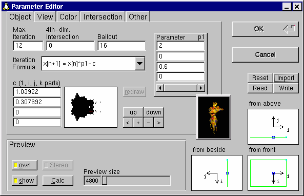
The so-called "Parameter Editor" dialog opens, which looks as follows
(shown here: X-Window-version, the tab "Object" is selected. The small black
window is the Julia Preview window, which is freely movable.):
In this dialog you can specify all parameters the are used to calculate
the image. Additionally, you can get a preview for the parameters entered
currently.
Using the tabs, you can select which kind of parameters to change:
- Object: The fractal parameters which are responsible for the shape of the object
- View: Parameters like the view point, zoom, lighting and 3d-stereo
- Color: The (true color!) palette of the image and the color formula, which relates the palette to the object.
- Intersection: Here you can cut away parts of the object (define intersection planes) to view the interior of the fractal.
- Other: All other parameters like resolution of the image, ambient light, anti-aliasing and Phong highlight
Nevertheless which tab you select, there's always the Preview window, the view selectors ("from beside", "from above" and "from front") and the action buttons ("Reset", "Import", "Read" and "Write") accessible. These elements are explained in the following.
The fractal is calculated as it would look like for the currently chosen
parameters in the Preview window. This is good for experimenting, because
it is often difficult to predict the effect of changing a parameter.
The button "Calc" calculates the preview and shows it right of it. If
the button "own" is active when you press "Calc" (active = yellow light),
the currently entered parameters are used for the preview (of course, except
resolution and anti-aliasing). If "own" is not active, a standardized view
of the fractal is calculated. This can be useful if you, for example, have
"lost your way", or by error selected black as the only color.
If there's entered a non-zero "interocular distance" in the View Editor,
you can choose a stereo preview using the button "Stereo". It's slower,
but three dimensionally. By the way, in that case the real image will be
in stereo always.
The button "show" shows/hides the Julia Preview window.
Actually, the view selectors are an addition to the View Editor, but because there is not enough space, they've been placed in the common area of the Parameter Editor. For how to use them, see explanation of View Editor.
The action buttons correspond to the commands in the "Parameters" menu, so they allow to read an INI file, write the parameters (or some of them) to an INI file, to reset the parameters or to import them from a PNG file. These actions all refer to the Parameter Editor, so if you import parameters and leave the Editor by selecting "Cancel", the original parameters are restored.
The Object Editor
In this dialog you can specify the fractal data of the object. This
data determines the shape of the fractal. You can enter values for following
keywords: Max. Iteration (maxiter),
4th-dim. Intersection (lvalue),
Bailout,
Iteration Formula and
c.
(See their description in Section 4.1).
If an Iteration Formula is selected which needs an additional parameter p1, a group of 4 value inputs is shown in which you can enter values for this parameter (the 1, i, j and k parts of the parameter).
You see a Mandel Preview which shows the Mandelbrot set (or, more exactly, two dimensional intersections of the four dimensional generalization of the Mandelbrot set). This set can be seen as a map for "Julia sets" (the objects being calculated by Quat). The red cross marks the selected point c. Every point c generates another Julia set. Points that lie in the Mandelbrot set (the black figure) lead to connected Julia sets, the other case they are split up.
You can click or drag with the mouse into the Mandelbrot Preview to
move the red cross. The values for the first two parts of c are updated
accordingly.
If it's necessary to update the Mandel Preview, it gets a red border.
Then you can click the button "redraw". This is necessary, if, for example,
one of the parameters maxiter, bailout or the last two parts of
c has been changed.
The six buttons right of the Mandel Preview serve the navigation in the
Mandelbrot Preview. You can move and zoom the section of the Mandelbrot set
that is shown.
The button "up" moves the viewable section up, "down" moves it down.
The button on the left, "<", moves left, ">" moves right. The two buttons
in the middle zoom in "+" and out "-".
The View Editor
The Parameter Editor with selected View tab looks as follows (shown:
Linux version)
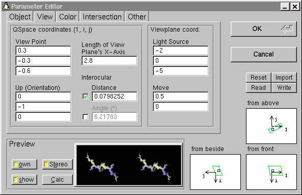
Here is the place to define how the object should be viewed. A view plane (on which the fractal gets projected) is defined by the parameters View Point, Up (Orientation), Move, Length of View Plane's X-Axis and Interocular Distance. The Light Source is also defined. (See descriptions in Section 4.1).
Below the edit control for "interocular distance" there is an angle shown. You can choose whether to keep the distance or the angle constant while changing the viewpoint. (By activating the corresponding checkbox.) The angle should be between 5 and 8 degrees if you want to create a 3D stereo image pair. If interocular is zero (and thus the angle is also zero), a 2D projection of the fractal object is generated.
Because it would be boring if you could only enter values you could
also enter in a text editor (INI file), there are three views of the view
point in the Parameter Editor. (You look at it "from above", "from beside"
and "from front".) The black arrows are the axes in Quaternion space (or
the three-dimensional sub-space defined by 4th-dim. Intersection
[Object Editor].) "1"
is the usual real axis, "i" the imaginary axis (same as with complex numbers;
These two are used by every 2D fractal program) and "j" points into the
third dimension (there is no "k" axis as the value for k is constant
[=4th-dim. Intersection]).
The arrows point in the direction of positive values, the length of
an arrows corresponds to the length 2 in Q-space.
The blue rectangle marks the view point, the green rectangle shows
the size of the view plane. You can click into the blue rectangle and drag
it to a position of your choice to change the view point. Some positions
are not defined (if the view point is (0,0,0) or if the up vector is
perpendicular to the view plane). In this case the controls which are responsible
for it are highlighted red.
The small cyan circle is the origin of the view coordinate system (=
the upper left point on screen)
The Color Editor:
Here's a screenshot of the Parameter Editor with selected Color tab
(Linux version):
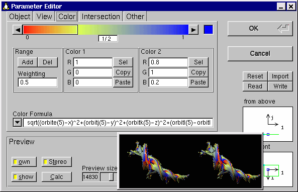
If you want to specify colors (or better, color ranges), do it here. At the top you see a scroll bar which you can use to select the color range you want to edit. You can either click directly on the color bar to edit, or use the arrow buttons next to it.
A color range is a part of the palette that begins with a color (Color 1) and fades smoothly into another color (Color 2).
Below the color bar, in the left column, there are two buttons, "Add" and "Del". "Add" adds a color range before the current position in the palette, "Del" deletes the active color range. There has to be at least one color range, and not more than 30. For each color range you can enter values for the start color ("Color 1"), the end color ("Color 2") and a weighting for the color range. The weighting defines how much of the palette is made of the selected color range. This value must not be zero. (See also section 4.2).
If you click the button "Sel" next to each color, you get a color selection dialog. If you don't want to create a color range but only a color, set both colors (Color 1 and Color 2) of the color range to the same values.
"Copy" copies the corresponding color into the clipboard (not into the global one of Windows/X, but into the rectangle in the upper right corner). "Paste" replaces the corresponding color with the color in the clipboard.
Below you can enter the Color Formula either directly or by choosing
one of the predefined formulas. (Also see key word
"colorscheme")
A Color Formula establishes the connection between certain parameters
of the fractal (for example, the QSpace coordinates of the object point
"x", "y" and "z") and the color palette as displayed in the color bar.
The left side of the color bar corresponds to "0", the right side to "1".
|
For example, if you start from the default blue sphere (Choose "Reset")
and simply enter "x"
as Color Formula, the palette gets "mapped" from left to right
onto the sphere. (Press Calc to generate a Preview) If you don't like that the palette starts over in the middle of the sphere, try "x+0.5" as the Color Formula. Now (after calculating the Preview) all the colors are shifted to the left. That's not quite what we wanted, we have to stretch the mapping a bit: Now try "0.8*x+0.5". The area in the middle that we want to cover the whole sphere is bigger, but not big enough. After some experimenting with the factor before the "x", we find that "0.5*x+0.5" does what we want. It maps the entire palette from left to right onto the sphere. You can then change the palette, and see that the colors are independant of their "mapping" and vice-versa. And you can try the same with "y" or "x+y" as a starting point. |
The Intersection Editor:
A screenshot of the Intersection Editor (Linux version):

Is used to define intersection planes. The scroll bar on the left has the same purpose as the one in the "Color Editor" described above: to select the object to edit. The buttons "Add" and "Del" also work like above, one adds a new plane, the other deletes the selected plane. There may be between 0 and 20 intersection planes. A plane is defined by its normal vector (pointing into the half-space in that the object should disappear) which must not be zero, and a point on that plane. (See also section 4.3)

Other Parameters are
Image Resolution,
Phong Highlight,
Ambient Light and
Antialiasing.
See section
4.4 for the first one, and section
4.1
for the last three.
In the Dialog there are five buttons (Resolution shortcuts). If you
hit one of them the resolution is set accordingly to the button hit.
ZBuffer menu:
To learn more about ZBuffers, please read section 2.3. The commands in this menu are for opening, saving and closing a ZBuffer. They have the same meaning as the commands for images, except that they refer to the ZBuffer, of course.
Help menu:
Help | Manual
Shows the documentation you are reading at the moment.
Help | About
Shows information about Quat.
3.2 Using the text only version
(Not applicable to versions with user interface.)Quat understands following parameters, which are given in the command-line:
| -i <ini file> | calculates an image from an ini file. (Ini files are used for feeding Quat with the values it needs to start a calculation) |
| -z <ini file> | calculates a Zbuffer (suffix ZPN) from an ini file. |
| -i <zpn file> | generates an image by using a precalculated Z buffer. (This of course is much faster than calculate from an ini file.) |
| -i <zpn file> <ini file> | generates an image from a Z buffer, but replaces certain parameters (coloring e.g.) with the values given in the ini file. |
| -p <png or zpn file> | reads the parameters that have been used to calculate the image/zbuffer and writes them to an ini file. |
| -c <png or zpn file> | continues calculation of an unfinished image. The ini file that has been used to generate the image is not needed. |
| -h | shows short information. |
A call looks like this:
quat -i test.ini
A calculation is stopped by
- DOS version: pressing a key
- other text versions: (turning off the computer). It isn't possible to terminate the text version since I don't know how to access the keyboard in a way that works on all system platforms (ANSI C)... :-(